Preparation steps
Before performing the unloading process, need to be prepared the necessary tools and equipment. This is so the time required is not lost because they have to find a tool or equipment.
Tools and equipment needed are:
a) Jack car and strut / jack stand
b) transmission jack as shown below.
Type of hydraulic jack, but some are using the screw. This becomes very important tool in the dismantling and installation of transmission. Because the position and the transmission will complicate the process of installation or demolition. Besides the safety of workers will be very harmful without this jack, and also the accuracy of the transmission installation.
a) The tool box containing the required key
b) work lights to light considering the position under the vehicle yangcenderung transmission.
c) Pump transmission lubrication oil filler and oil lubricants.
d) Body of the old lubricant reservoir.
e) Vet gravit and cloth / cotton waste.
Safety:
Each practice includes the demolition and installation of transmission, must always put the good work of salvation for the human and the workpiece. Therefore accuracy both before and at work is indispensable. Always keep all safe working conditions, such as for example to avoid the oil spill on the floor. In addition to causing discomfort in the works, the oil can cause crashing.
Demolition process:
a) Disconnect the negative battery terminal, is to guard against short-circuit current work.
b) Raise the car using a jack and plug the high jackstand removal to make room for the free movement of workers and the demolition and installation of transmission.
c) Remove the rubber cover stick / lever / handle the transmission gear shifting. See figure 16 below. By removing the fastening bolts.
d) Remove the transmission handles gear shifting, by removing the fastening bolts and lift out.
e) Remove the starter motor, which is off the wires and fastening bolts.
f) Remove the transmission lubricating oil, by opening the tap bolts, and prepare a lubricating oil tank. After finished, replace the screw tap and remove the lubricating oil tank, not to spill. If used to clean the spill.
g) Remove the propeller keporos connection, so that when the installation is not mistakenly marked before being released. As shown in FIG.
h) Remove the speedometer cable and reverse light wires from the terminal.
i) Remove the clutch cable from the lever liberator
j) Remove the handle and exhaust clamps associated with the transmission.
k) Place the transmission jack well, if necessary fastening with bolts or chains are available. This is to avoid the transmission falls off when the bolt fastening.
l) Remove the transmission mounting.m) Loosen the bolts fastening the transmission home. Consider whether the transmission remains in a flat position or not, when tilted like the image 20, then raise the jack.n) When the transmission is flat with the correct position, then remove the bolts fastening the transmission. Once again, note the flat position transsmisi.o)
Pull the transmission towards the rear of the car, until the end of the
transmission shaft pirmer off, and then lower the transmission jack to
pelan2 expected when pulled out from under the car is concerned.p) Reduce the transmission of the jack.
Examination:a) Check the leakage of lubricating oil on the transmission input shaft seal. If there are signs of leakage instead of his seal. Oil
leak is in addition to causing lack of air-transmitted quantity of
lubricating oil, also when taxable koling be causing the clutch plate
slip.b) Examination of lubricant oil leakage is also on the crankshaft seal.c) Examination of the wear of the clutch cable connection, and congestion.d) Check bearing road, the play is still smooth or broken. If damaged replace a new one.
Installation instructions:a)
Lubricate using a grease-resistant graphite or hot grease in the
bearings pilt on the fly wheel, boss conductor groove bearing press,
and the transmission shaft groove. Look at the picture 19. besides that it is also at the end of the clutch cable.The parts are given a Vet
b)
Install / Rev transmission on transmission jack, like the previous
position of the transmission must be flat, especially the transmission
input shaft. And the transmission belt properly on the jack in position when installed.c) Put the jack under the car and the transmission kekolong.d) Raise the jack until the correct input shaft to pilot bearing.e) Encourage the transmission slowly to match the end of the transmission input shaft pilot bearing on the fly wheel. After the fitting, slide the transmission back to the house to sit with ease. In this process should never be forced out by pressing the home life of the transmission bolts prngikat.f) Install the transmission mounting bolts and fastener. Harden according to the moment of hardening of the manual.g) Replace the motor and its starter cord.h) Install the propeller shaft in accordance with the sign made.i) Connect the speedometer cable and reverse cable and exhaust clamps.j) Fill the transmission lubricant.k) Install the clutch cable and sets the height and the freedom of the clutch pedal. See figure 22 below. Pedal height = 150.8 mm, and its freedom = 20-35 mm.l) Place the transmission shift handle with a rubber cover.m) Lower car from jack stands.n) Turn on the car, try adjusting the clutch and transmission work.o) Clean tools and equipment used.
Compressor is divided into two parts, namely:
1) Compressor
2) Clutch magnet (Magnetic Clutch)
1) Compressor
The compressor is driven by the fan belt from engine pulley. This will drive the rotation of the compressor piston / vane and piston movements / vane will cause pressure on the gaseous refrigerant so that the pressure is increased which in itself also will increase its temperature.
These types of compressors can be divided into:
Reciprocating Type:
Crank type
Swash plate type
Rotary type
Through vane type
2) Clutch magnet (Magnetic Clutch)
Magnetic coupling is a compressor which supplies a tool used to remove and connect the compressor to the engine speed. Equipment point is: Stator, rotor and pressure plate. Working system of this device is an electro magnetic.
How it works:
Compressor pulleys are always spinning by the rotation of the engine through the fan belt when the engine life. AC switch in position off, the compressor will not spin, and the compressor will only spin when the AC switch in the position to live (on) this is caused by an electric current flowing to the stator coil will change the stator coil into an electric magnet that will attract pressure plate and the field tangent will rub and stick together in one unit (Clutch assembly) rotating compressor.
a) Three-Speed Transmission with Slidingmesh
This transmission has been used in motor vehicles in the 1930's. Here is not going to learn the history of the transmission, but this model easier to understand the working principle of a transmission, in particular how the process of removal / transfer of power / moment carried in a motor vehicle transmission. A simple schematic model of this transmission, can be seen in the picture below. This transmission uses gears spur gear type and is made with three separate shafts, namely:
(1) the primary shaft (4) (primary shaft) - the shaft that receives the first rotary motion of the clutch.
(2) intermediate shaft (2) (layshaft / countershaft) - that is where the counter gears are placed.
(3) the main shaft (9) (mainshaft) - the shaft out of the transmission, transfer power to other system components.
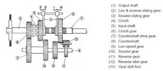
Primary shaft which is connected to the clutch, dipasaang dead ends with the player pinion fixed to the transmission system, and provide round the gears on the intermediate shaft. While the main shaft gears can be shifted on-slide individually and can be connected with the existing gear on intermediate shaft is made to rotate together. Shifting gears on the main shaft, use the shift (8) passed to the selector fork (6).
In the neutral position, all the gears on the main shaft is positioned not associated with the existing gear on intermediate shaft. Rotation of the primary shaft forwarded to the gears on the intermediate shaft, but do not rotate the gear on the main shaft. In other words, rotation of the primary shaft is not transferred to the main shaft / output transmission.
Tooth position First, the gears on the main shaft A is shifted up a gear connected to the intermediate shaft B to see the image in Figure 5 or 6 parts number 11. C while the gears in neutral. In this position, means the rotation of the gear shaft E in the primary, F transferred to the gear wheel mounted gear off with B or F gear wheel gear B. Rotation of the gear to gear B is moved and passed keporos A main transmission output. Because the player gear (driver) the number of teeth less (ie gears E and B) of the playing gear (driven), then there is a decrease or reduction of spin-rise
Calculation
of spin reduction is done by comparing the number of teeth on gears
that rotated compared to the number of gear teeth on the player.So the formula comparison teeth as follows:Comparison Dental First = F / E x A / B = 40/20 x 40/20 = 4.Figure
4 shows that the moment the transmission output would be 4 times
greater than the moment at the input shaft, but the speed /
transmission output shaft rotation putraran ¼ of the input shaft. This means that the same engine rpm, vehicle speed is slower. It is necessary to lift the burden of a larger vehicle with a fixed power.Both the position of teeth, the second speed gear A on the release of the gear B, and C are connected keroda gear teeth D. So
that the flow of energy / rotation of the gear to gear E F, F spin gear
with gear D, then D rotating gears gears C and forwarded to the
transmission output shaft.Calculation of spin reduction equal to the first gear position above, namely:Comparison of Dental Both = F / A x C / D = 40/20 x 30/30 = 2.Figure
2 shows that the moment the transmission output would be 2 times larger
than the moment at the input shaft, but the speed / transmission output
shaft rotation putraran ½ of the input shaft. This means that the same engine rpm, vehicle speed two times faster in comparing the first gear position.Third
tooth or the highest position, the position is a permanent free gear,
gear C is removed from D and shifted gears are connected directly
through a dog clutch with gear E. thus the input shaft rotation with output shaft rotation or 1: 1.Position Reverse / Reverse, is required to drive the vehicle backward. In
this position C shifted gears in neutral and shifted gears A gear
associated with H, spin gear to gear E F G next gear that rotates
together with the gears rotate gears F H, and H gears A gear wheel and the transmission output keporos forwarded by the reverse rotation of the input shaft. When the number of G is 10 teeth, thenComparison of Dental Both = F / E x H / G x A / H = F / E x A / G = 40/20 x 40/10 = 8.Figure
8 shows that the moment the transmission output will be 8 times larger
than the moment at the input shaft, but the speed / rotation
transmission output shaft 1/8 of putraran input shaft. This means that the same engine rpm, vehicle speed of 1/8 more slowly.
b) Unit Selector MechanismAs
mentioned in the description above, the existing transmission equipment
which is used to operate the transmission onalkan, ie to change from
one speed to another kekecepatan. Gears
in the transfer should not be double splicing, such as gears A gear
associated with H or B, then C is also associated gear to gear E or D. When
this happens, the consequences could be fatal, if not locked or can not
spin all, mak damage can occur on one pair of gears.To prevent these problems, the manual transmission is equipped with a device selector mechanism, as shown in the image below.
Fork selector (selector fork) on a drawing, used to shift the gears on the main shaft. In the three-speed transmission plus one reverse speed selector fork requires two pieces. The bottom of the fork selectors associated with the gears, while the upper part associated with a movable handle the transmission of the wheelhouse.
Each transmission must be equipped with pealatan (a) to put the gear selector to avoid air-geraksendiri, and (b) to prevent the two gears are connected simultaneously. So b serves to hold the position of the gears. In this position, if one gear is moved, then it is locked by a mechanism other sectors, such as was seen in the picture c. Pennguncian through design that is placed between the plunger rod selector. Thus if one of the gears will be connected, then the other is locked in a neutral position. A gear when the gear is connected then C is locked in a neutral position. So that the selector mechanism likely be attached two gears simultaneously can be prevented.
c) Transmission 4-speed synchromesh
The concept of energy flow / moments similar to those used in the above three-speed transmission. The difference in transmission does not use the system except for the reverse sliding gear. This condition allows the used to be a form other than spur gears, both forms of the double helical or helical. These teeth form in addition to the more powerful because more extensive contact between his teeth, his voice is also more refined.
Construction of this transmission, all the gears on the main shaft (main shaft) connected free. While the main shaft connected sychromesh sliding.

Materials and equipment:
A. Key to set the injection nozzle
2. Injection nozzle tester
3. injection nozzle
4. Step shim job setter Injection Pressure Test: Test the injection pressure tester 1.Pompakan handle several times in order to inject diesel fuel from the nozzle fitting and then harden fitting
2.Pasang injection nozzle at the injection nozzle tester and remove air from the union nut. 3.Pompakan tester handle several times as fast as possible to clean the carbon from the injection port
4.Pompakan tester handle slowly while observing prssure gauge.
5.Baca pressure gauge when the pressure begins to drop pressure injection opening: a new nozzle: ................ kg/cm2 nozzle length: ................ kg/cm2 nozzle works perfectly if the hissing sound and open it when the pressure is not within specifications instead of unloading the shim adjusting the nozzle holder at the top of the opening pressure adjustment spring pressure (opening pressure): ....... kg/cm2
6.Ada various shim thickness of 0.025 mm setter each press changes the injection of about ........... kg/cm2 and only one setter shim should be used
7.Harus no form of droplets after injection 8.Mengetes a.Pompa spray tester handle 15 to 60 times (nozzle older models) or 30 to 60 times (new model nozzle) per minute b.Periksa form of sprays, spray when the form is incorrect for spraying the nozzle should be replaced or cleaned
Injection nozzle section receiving the high-pressure fuel and injecting into the combustion chamber. When the pressure is pumped by the fuel injection pump to be larger than the spring load pressure, the nozzle needle push energy upwards. This causes the spring to be compressed and the pressure of fuel injected into the combustion chamber. Injection pressure can be tuned by adjusting shim thickness to distinguish, which effectively turns the load on the spring.
This accepts the high pressured parts fuel and injects it into combustion chamber. When the fuel pump Pressure Pumped by hypodermic Becomes bigger than burden of spiral spring pressure, its energy will push the needle nozzle to up. This matter Causes the spiral spring [of] pressure and the solid Becomes fuelis injected to combustion chamber. Hypodermic pressure can be switched on by differentiating thick [of] the which swictch Effectively shim alters the burden [of] [at] spiral spring
A. Spring pressure (Pressure spring)
B. nozzle needle
C. Bodi nozzle
D. Shim setter
1. Pressure Spring
2. Tail the nozzle
3. Bodi Nozzle
4. Shi
Indonesia's new cars are using a machine with a propulsion system valve, VVT-i, VTEC, valvetronik or VANOS. Toyota generally give the name of VVT-I engine. While the renamed Honda VTEC. VVT-i system VVT-i (Variable Valve Timing - Intelligent) is a series of devices to control the camshaft drive. The idea is to adjust the valve opening time with the condition of the engine. So that optimum torque can be obtained at each speed level. While saving fuel and reducing exhaust emissions. In the Toyota engine, this system was applied to the intake valve. The exposure time can be varied over a range of camshaft 60 degrees.
For example, at the start, a cold engine and stationary engine without a load, timing set back 30 degrees. This method would eliminate the overlap. Namely
events in and exhaust valves open simultaneously at the end of the
drainage step into the new valve will open some time after the exhaust
valve is fully closed. Logically, in these conditions the engine does not need extra work. By closing the exhaust valve, no fuel is wasted time getting sucked into the engine. Fuel
consumption and engine become more efficient when there are loads environment.while friendly, will forward 30 degrees timing. Degree of overlapping increases. The goal is to help drive the exhaust gas heat plus a mixture of fuel and air intake. Moreover, time is also increased due to compression of the inlet valve closes too early. The effect, so better volumetric efficiency. To that end, there's VVT-i controller on the intake camshaft timing gear. These tools consist of housing (house), then there is room inside the oil to move the vane (vane). Propeller is connected to the camshaft. In it there are two lines of each oil to the oil chamber in the house VVT-i controller. Different from the oil line is, vane will set the valve opening time. Timing advance position to come forward to fill the oil to the rear of each vane blades.
So that the vane will move forward and timing position had come forward 30 degrees. Own the oil pressure supplied by the Oil Control Valve camshaft timing is adjusted by the engine ECU. In contrast, for conditions retard (backward), the space in front of the vane position will be filled and timing back. Meanwhile, if required at standard conditions, there is a pin that will lock the fixed vane position is in the middle. Actually there is a more sophisticated system, called VVTL-i (Variable Valve Timing-Intelligent Lift). In addition to playing time of valve opening, high, too differentiated. The
advanced technology VTEC Variable Valve Timing and Lift Electronic
Controlled (VTEC) Honda innovation results showing different
mechanisms. The main difference is the inclusion of valve movement. In the 16 valve engine, there are two each incoming and exhaust valves in each cylinder. VTEC is applied only on the intake valve. This valve controls the efficiency of the engine more powerful. The
assumption, does not require the opening of the disposal process for
the current variable valve exhaust, engine work will be more lightly. In the VTEC engine, the second intake valve does not always move together. For example, at low speed there is only one valve is open. Opening is relatively small because the characters are punched camshaft valve is suitable for low speed. This condition is considered appropriate for the machine. Due to the low round of the air supply does not need much. In addition, there could be air turbulence to help mix the fuel. Machine so economical, efficient, environmentally friendly too. As engine speed increased, the need for the air supply is also increasing. Directly answered by the second valve. A larger opening for nok chamshaft have a higher degree of character. Fun, had joined the first valve to open wider. This is due to any pin that connects the rocker arm and push the pin. Will automatically lock the pin was the second rocker arm. Because the second rocker arm actuated by a camshaft duration peak is higher, so it follows the movement of the first valve. In addition there are also VTEC i-VTEC (intelligent VTEC), which also includes the mechanism of ignition advance and rewind. Of maximize results to improve the efficiency of the engine.
Many students are asking "how to work matic CVT on that? Here's an explanation how the CVT works may be many other school vocational students also do not understand the workings of the machine automatic or CVT (Continuously varible Transmission) on a motorcycle. It was much simpler than a conventional engine or transmitting machine.
All components contained in the box CVT CVT or the visible form is a swing arm automatic motorcycle left us, who look so big and heavy. There are three main components, namely the front puly (Drive Pulley), rear puly (Driven Pulley) and v-belt. Puly front connected to the engine crankshaft (crutch-as), while puly as-is connected to the rear wheels. Puly connecting the front and rear puly is a v-belt.
At the time of stationary or low speed, puly front has a smaller radius than the rear or puly lightweight gear ratios.
Along with increasing engine speed (rpm), then the radius should puly joined up front while the rear puly actually smaller or equal to the weight of the gear ratio. To work v-belt connecting the two puly just so they can be run in turn. So the next time puly enlarged causing the rear puly is smaller because of the insistence of the v-belt, because the length of v-belt is always the same in this process.
Because the CVT is a linear work, then the automatic machine can produce a smooth acceleration without losing power.


